Why does one batch come out of the press with a flat rim and the next with ripples? A Deep Drawn Parts Manufacturer Stops Wrinkling in Two Steps. First, use a blank holder to grip the edge of the blank. Then adjust that holding force to the metal. Years on a press floor teach a quick lesson. A wrinkle is a force issue, not a surface problem. As it slides inward, flat metal folds down when nothing is holding it down.
The article demonstrates how a flange wrinkle begins. It also has holding force, corner radius, draw staging, material restrictions, and the tests to show a part is clean.
What Is Deep Drawing, and Where Does the Wrinkle Begin?
A flat metal blank is pressed through a die during the stamping process known as deep drawing. The blank part forms an open hollow shape like a cylinder, box, or stepped shape.
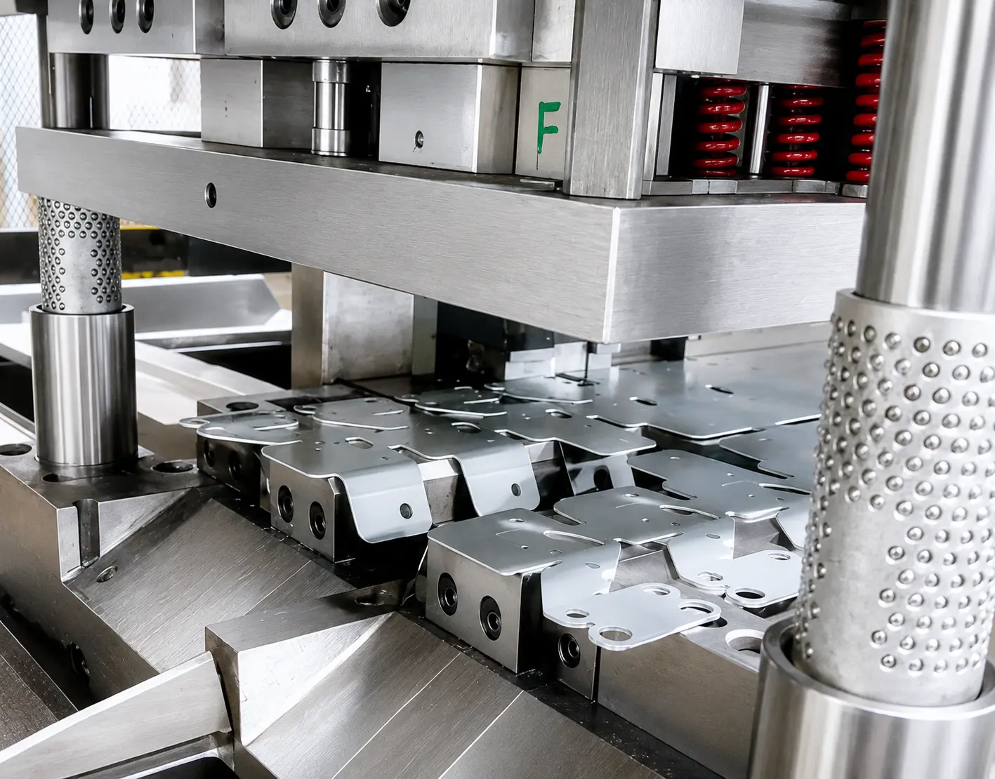
Punch pushes down the blank. It takes on the shape of the die. The blank holder (sometimes termed a sleeve) grips the edges. This grip maintains control over the metal feeding.
The wrinkle is on the flange, not the wall. The flat rim outside the die is called the flange. That rim must shrink as the blank draws inward. Metal is compressed by shrinking. The rim folds without support.
Core Elements of the Deep Draw Stamping Process
| Element | Job in the draw | Link to wrinkling |
| Flat blank | Starting metal, cut to size | Bigger blanks carry more rim stress |
| Punch | Pushes metal into the die | Its corner radius sets tear risk |
| Die | Forms the outer shape | Its entry radius guides metal flow |
| Blank holder | Grips the blank edges | Main wrinkle control |
| Lubricant | Cuts friction at contact faces | Lets metal slide at lower force |
What Actually Causes a Wrinkle in the Flange?
Flange wrinkle is the result of excessive tangential compressive stress in the flange region. That stress makes the metal unstable, and thus it buckles. Tangential compressive stress is merely a squeeze round the rim.
Think of a wrinkle as a difficulty in stability. A thin unsupported sheet is analogous to a long, slender column. Won’t crush. It tilts sideways.
This is counted when you repair it. No, polishing the die won’t help. Slowing the press won’t do it. Only support alters the output.
How Much Blank Holder Force Is the Right Amount?
The correct blank holder force is the minimal force necessary to maintain the rim flat. But it must still allow metal to flow into the die. There is not a single number. The force is determined for each job, depending on material grade, thickness, and draw depth.
Neither extreme works. Not enough force, and the rim folds over. Too much force grips the sheet. Then metal can not feed in. At the base of the wall, around the corners of the die, and at wall splits, pull grows.
A reputable deep drawn parts manufacturer will see these two boundaries as a window, not a goal. It’s simpler to broaden the window than to strike one perfect number. A better lubricant helps. A softer grade helps. A greater die radius helps.
Diagnosing Common Draw Defects
| Symptom | Likely cause | What to do |
| Folds around the rim | Holding force too low | Raise force in small steps; check holder gap |
| Split at the wall base | Holding force too high | Lower force; add lubricant; open the die radius |
| Ripples in the cup wall | Radius too large; metal unsupported | Cut punch radius; add a redraw stage |
| Uneven flange height | Blank off-centre or uneven force | Re-centre the blank; check holder flatness |
Forming sources suggest a usual starting pressure around 1 to 3% of the tensile strength of the metal. As a preliminary guess, treat that. The ultimate value is established via trial and simulation runs.
Why Does Corner Radius Decide Between Wrinkles and Cracks?
The corner radius of the punch and die must be at least 4 times the material thickness. Below that, the metal bends too sharply at the die mouth. Sharp turns create a pull at the wall’s foundation. This is precisely what a cracked part does.
Lubricant works with the radius. Less resistance, less pull on the wall. The lubricant and the radius together enable the press to operate with a reduced clamping force.
So force is a trap in itself. Lift the grip to kill a wrinkle, and the failure merely shifts. A split appears at the corner where it departs the rim.
When Is One Draw Not Enough?
When the necessary reduction exceeds the limiting draw ratio of the metal, one draw is insufficient. Soft, ductile grades provide a first-draw ratio of 2.0 to 2.3. The harder grades are towards the bottom, at 1.6 to 2.0.
The staging is on a descending curve. Draw reduction charts like those in The Fabricator indicate that the initial draw is the biggest decrease. Because the metal has already hardened, further draws require less time.
Choosing a Die Configuration by Volume and Shape
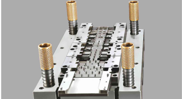
| Die type | Best suited to | Typical output | Precision note |
| Single process | First draw of simple cylinders | Low volume | Simple build, low tooling cost |
| Compound | Small and medium parts, such as capacitor housings | Medium volume | Blanking plus drawing, ±0.1 mm |
| Progressive | Mass-made automotive parts | Up to 800 pieces per hour | Trim, draw, and punch in sequence |
| Continuous | Large, complex parts | Varies by part size | A robot moves the blank between stations |
Multi-stage deep drawing uses a separate tool for each draw. No joint is added, so the part has seamless one-piece construction. There is no weld line to leak or crack. Progressive die tooling suits steady, high-volume runs where setup time costs money.
How Does Material Choice Move the Safe Force Window?
Wrinkle threshold is altered by material selection. All of the dimensions of a metal are within safe ranges, including how far it extends, its thickness, and its strength. Common grades include low carbon steel (SPCC and SPCD), stainless steel 304 and 316, aluminum alloy 5052 and 6061, and copper alloy.
Every year, more high-strength steel is utilized, primarily for lighter parts. HSS is tough, but it doesn’t bend much before it breaks. Between too loose and too tight, the gap is becoming narrower.
A thin sheet acts in the same manner. A narrow rim folds under less stress and hence requires support sooner. The thickest, softest, best-oiled stock offers the biggest margin of error.
How Is a Wrinkle-Free Result Verified, Not Just Claimed?
The stated inspection limitations are validated by a wrinkle-free outcome, not by sight alone. Tight dimensional tolerances are meaningless without a number and a sample rule behind them.
Dechen Metal Machining publishes its inspection standard for drawn work:
- Dimension tolerance: diameter ±0.1 mm, height ±0.1 mm
- Surface defects: no visible cracks or wrinkles; scratch depth 0.05 mm or less
- Mechanical properties: hardness test and hole expansion test to confirm ductility
- Batch consistency: first-piece check, plus sampling of at least 5% per batch
Hole expansion testing is the useful one here. It shows how far an edge stretches before it splits. That is a direct read of how much forming the metal has left to do. A deep drawn parts manufacturer that shares this data gives buyers something concrete to check.
What Defect Appears After the Wrinkle Is Gone?
Springback is the defect that appears once wrinkling is resolved. Metal stores spring during forming. It lets that spring go when the tool opens. The part then relaxes away from the die shape.
Springback is fixed by over-drawing or a follow-up shaping step. Overdrawing slightly past the target, so the relaxed part lands on size. Stronger grades spring back more. Plan for it during tool design, not after the first run.
What Should a Deep Drawn Parts Manufacturer Check Before Tooling?
Draw feasibility is settled before steel is cut, not during the first article. A short pre-tooling review removes most of the risk from a new job.
Pre-Tooling Checklist for Drawn Enclosures
- Check every corner radius against the final sheet thickness, using four times the thickness as the floor
- Lock the material grade and temper early, since force settings depend on it
- Compare the draw depth with the part diameter to set the number of stages
- Flag any flatness, sealing, or cosmetic face needs on the drawing
- Match the die type to the yearly volume before quoting tooling
- Mark, which dimensions are critical, so checks focus where it counts
Sealing faces require extra care on deep drawn enclosures. A rim that must seal has less room for waviness than a rim that gets trimmed off. The same goes for deep drawn housings that carry a press-fit lid.
Frequently Asked Questions
What causes wrinkling in deep drawn parts?
Wrinkling in deep-drawn parts is caused by excessive squeezing around the flange, which makes the sheet buckle. The rim must shrink as it feeds inward.
- Low blank holder force is the most common trigger
- A holder gap far wider than the sheet leaves the rim unsupported
- Deeper cavities pull more metal, so the risk goes up
How much blank holder force is enough?
Enough force is the lowest setting that keeps the rim flat while metal still flows into the die. References suggest starting near 1% to 3% of tensile strength, then adjusting by trial.
- Force depends on grade, thickness, and draw depth together
- Variable systems hold high early, then ease off as the rim shrinks
- Draw beads can guide flow without raising overall grip
Can wrinkling be fixed after the part is drawn?
Wrinkling cannot be reliably fixed after drawing because the fold is a permanent buckle. Ironing may flatten a light ripple, but thickness and grain are already disturbed
- Prevention costs far less than rework
- Heavy rim folds usually mean scrap
- Any wrinkle inside a sealing face should be rejected
What tolerance can deep drawn metal components hold?
Deep drawn metal components at Dechen Metal Machining are held to ±0.1 mm in diameter and ±0.1 mm in height. Surface limits allow no visible cracks or wrinkles, and the cap scratch depth is at 0.05 mm.
- Compound dies reach ±0.1 mm on small and medium parts
- First-piece checks plus 5% batch sampling keep runs consistent
- Tighter features can be added by a later machining step
How deep can a part be drawn in one operation?
A part can usually be drawn in one hit when the draw ratio stays near 2.0 for ductile metals. Harder grades sit nearer 1.6. Past that, staging is needed.
- First draws take the largest cut; later redraws take less
- Annealing between stages restores ductility for deeper parts
- Depth is always judged against diameter, never on its own
Is deep drawing cheaper than machining a part from a solid?
Deep drawing is usually cheaper at volume and reduces scrap by 30% to 50% compared with machining or welding. Tooling costs more up front, so the savings depend on quantity.
- Machining suits, prototypes, and very small runs
- Drawing wins once the tooling cost is spread across a full run
- Drawn parts have no weld seam, so fewer leak tests fail
Conclusion
Wrinkle control comes down to balance. Grip the rim enough to stop folds. Keep the radius and lubricant right to protect the wall. Stage the draw when depth calls for it. Then prove the result with numbers. That is how to judge any deep drawn parts manufacturer. For custom deep drawn parts, Dechen Metal Machining publishes a standard you can check: ±0.1 mm on diameter and height, scratch depth under 0.05 mm, and 5% batch sampling. Send a drawing for review.